
Page 10 - ABB_Welcome-Example-systems
P. 10
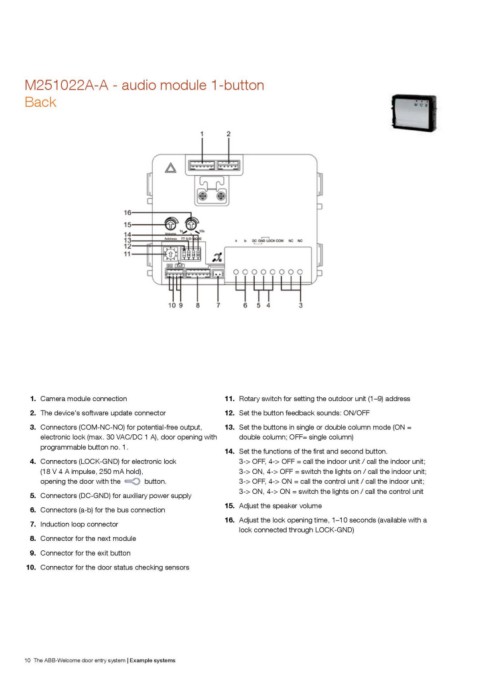
M251022A-A - audio module 1-button
Back

1. Camera module connection                                  11. Rotary switch for setting the outdoor unit (1–9) address

2. The device's software update connector                    12. Set the button feedback sounds: ON/OFF

3. Connectors (COM-NC-NO) for potential-free output,         13. Set the buttons in single or double column mode (ON =
    electronic lock (max. 30 VAC/DC 1 A), door opening with        double column; OFF= single column)
    programmable button no. 1.
                                                             14. 5GV VJG HWPEVKQPU QH VJG ƂTUV CPF UGEQPF DWVVQP
4. Connectors (LOCK-GND) for electronic lock                       3-> OFF, 4-> OFF = call the indoor unit / call the indoor unit;
                                                                   3-> ON, 4-> OFF = switch the lights on / call the indoor unit;
(18 V 4 A impulse, 250 mA hold),                                   3-> OFF, 4-> ON = call the control unit / call the indoor unit;
                                                                   3-> ON, 4-> ON = switch the lights on / call the control unit
opening the door with the         button.
                                                             15. Adjust the speaker volume
5. Connectors (DC-GND) for auxiliary power supply
                                                             16. Adjust the lock opening time, 1–10 seconds (available with a
6. Connectors (a-b) for the bus connection                         lock connected through LOCK-GND)

7. Induction loop connector

8. Connector for the next module

9. Connector for the exit button

10. Connector for the door status checking sensors

10 The ABB-Welcome door entry system | Example systems